


Reviewed by Jason Dong / Product Engineer
If you are planning a fertilizer granulation plant, the workshop is usually the largest single line item in your civil budget, and it is also the hardest to change once concrete is poured. This article gives you the reference dimensions EMCC uses to size workshop length, width, clear height, column grid and floor loads for granulation lines from 1 to 30 t/h — so you can check a proposed layout against real numbers before procurement, not after.
Which Inputs Decide Workshop Size Before Any Drawing Is Made?
Workshop planning should run in parallel with equipment selection, not after it. Five inputs fix the dimensions:
- Equipment dimensions and weight set foundation loads, clear height requirements and lifting access.
- Material properties — moisture content, flowability, stickiness and particle size — determine conveying methods and chute inclination angles.
- The process route, including drying, cooling, coating or fermentation, decides the functional zoning.
- Storage requirements: raw material storage cycle, finished product volume and packaging specifications fix the storage area.
- Environmental equipment: a pulse dust collector and a spray tower each claim their own footprint and height inside the building.
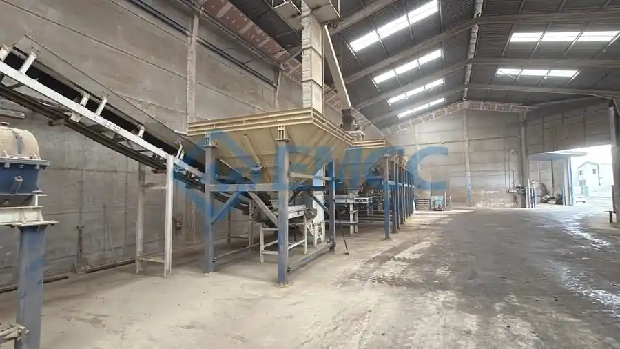
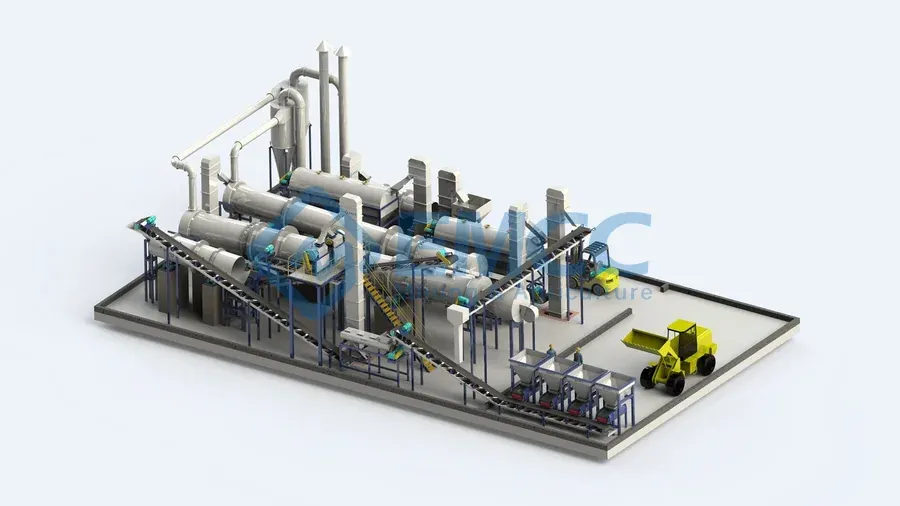
The common failure patterns behind undersized workshops are predictable: clear height too low for the elevator head or the dryer drum; a flat single-level layout that eats land while long-distance belts raise dust and run out of alignment; and fermentation, granulation and storage zones interfering with each other. The decision principle is simple — settle clear height and column grid span through 3D coordination at the equipment design stage. Never build the workshop first and pick equipment later.
How Much Floor Area Does Each Capacity Class Need?
The reference values below are based on common equipment models and standard process routes. Actual dimensions must be confirmed by 3D layout design on the selected equipment and process scheme.
| Process line type | Length × width | Reference clear height | Planning key points |
| 1–3 t/h disc granulation line | Approx. 36 m × 12 m | Eave ≥6.0 m | Elevator head clearance ≥7.0 m; gravity flow from disc to discharge belt |
| 5–10 t/h extrusion roller granulation line | Approx. 42 m × 15 m | Eave ≥7.5 m | Crushing/screening tower clearance ≥8.5 m; gravity flow to crusher |
| 10–20 t/h rotary drum granulation line | Approx. 72 m × 18 m | Eave ≥9.0 m | Granulator and dryer overhead; gravity flow from drum into dryer |
| Fermentation workshop (100,000 t/y) | Approx. 80 m × 30 m | Eave ≥6.5 m | Turner crane span and clearance; trough depth 1.5–2.0 m |
| Automated storage area | Approx. 48 m × 24 m | Eave ≥8.0 m | Stacker crane and rack height; forklift turning radius |
Three caveats matter when you compare these figures with your own plot. First, the areas above cover the main workshop only — they exclude raw material and finished product warehouses, office area and environmental facilities. Second, the bucket elevator of a rotary drum line can exceed 20 m, and a tower arrangement raises the building height accordingly. Third, if output targets keep slipping on an existing site, the constraint is often layout rather than equipment — see our analysis of why a compound fertilizer line fails to reach target output.
What Clear Height Must Each Zone Reach?
Clear height is where most planning mistakes happen, because it is cheap to fix on paper and expensive to fix on site.
- Ground-level single-level area: eave height ≥7.5 m, with maximum crane hook height ≥5.5 m.
- Granulation vertical frame or tower: eave height ≥12.5–14.0 m. Chute angle follows the material: granular ≥40°, powdery ≥50°, sticky ≥60°.
- Packaging and storage area: eave height ≥8.5 m for pallet racking and forklift clearance.
Organic fertilizer plants split differently: the high-temperature fermentation area needs ≥5 m, the production area (crushing, granulation, drying, packaging) needs ≥6 m, and the finished product warehouse needs ≥6 m.
Budget consequence: every 0.6 m of extra clear height adds roughly 8–10% to unit area construction cost. That is exactly why the height decision belongs at the equipment design stage, where a 3D model can verify elevator head clearance before the steel order is placed.
When Does Gravity Flow Actually Pay Off?
Gravity flow moves material through equipment elevation differences and can cut horizontal conveying belts — but only when three conditions hold.
- Material flowability: chute inclination angle ≥40° for granular material, ≥50° for powders, ≥60° for sticky materials, possibly with vibration assistance.
- Elevation difference: a vertical tower provides height but raises civil investment; a single-level layout with elevators and belts may be more economical.
- Capacity matching: below 5 t/h, a vertical tower is often not economically favorable.
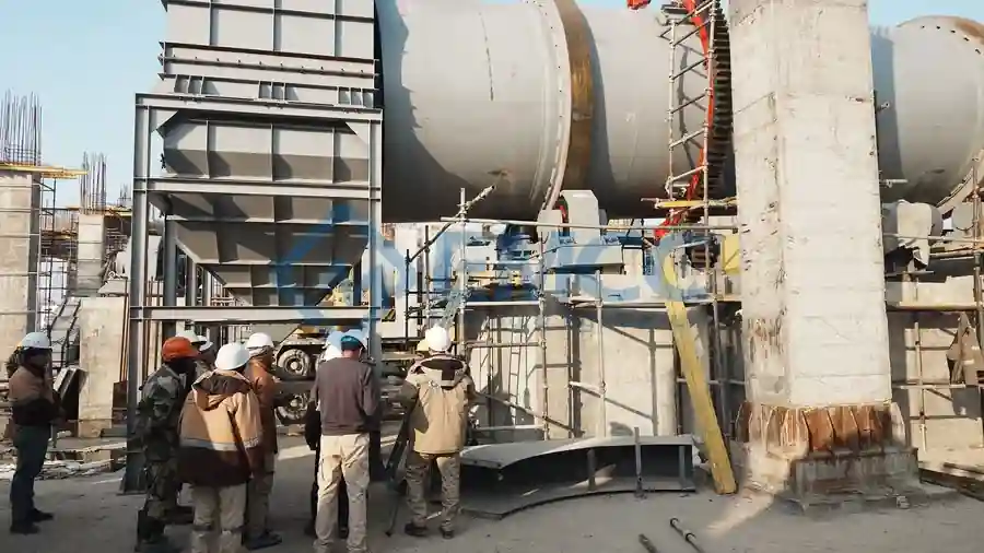
One structural point is easy to miss. The rotary drum granulator and the dryer drum generate significant dynamic loads in operation. Use an independent reinforced concrete gravity foundation, separated from the workshop steel structure column foundation, to isolate vibration transmission. Concrete strength grade must not be lower than C30, with thickness calculated from equipment weight and dynamic load factor, and a vibration isolation joint ≥50 mm wide between the equipment foundation and the column foundation.
What Maintenance Space Does the Line Need After Commissioning?
Five design points decide whether the line can be maintained, drained and kept clean after commissioning — none of them can be retrofitted cheaply.
- Crane rail: configure a 5–10 t electric single-girder overhead crane for lifting drum support rollers and reducers.
- Floor: wear-resistant, anti-corrosion hardening with a drainage slope of 1%–2%.
- Duct penetrations: insulate and rainproof the wall penetrations of induced draft and dust removal ducts to stop rainwater backflow.
- Doors: clear width and clear height ≥4.5 m for container trucks and loaders.
- Electrical and control rooms: independent compartments on the upwind side of the air intake, isolated from dust and corrosive gases.
What Column Grid and Floor Loads Does the Equipment Impose?
Column grid spacing follows the equipment layout scheme, not fixed values. A portal light steel structure is recommended: span 24.0 m (double span 48.0 m), column spacing 6.0 m or 7.5 m, finalized on the equipment layout drawing. Three equipment classes set the grid:
- Roller extrusion units 4–5 m long: column spacing of 6.0–7.5 m meets requirements.
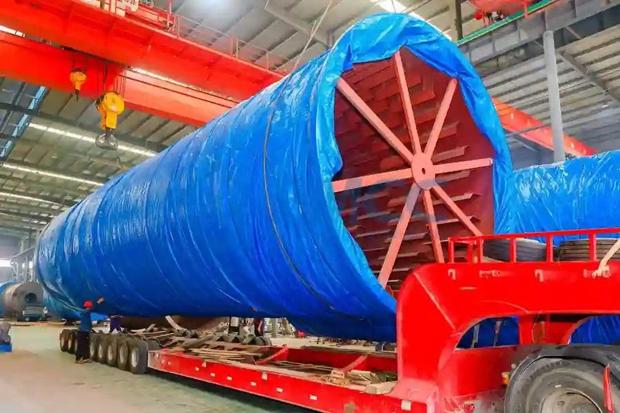
- Rotary drum granulators up to 8 m and dryer drums up to 20 m: column spacing must follow equipment length.
- Fermentation troughs 6–10 m wide: column spacing must match the trough width — a groove-type compost turner travels the full trough length, so no column may land inside it.
Functional floor loads and crane references:
| Functional section | Load reference (t/m²) | Crane reference | Notes |
| Automatic batching and crushing | ≥4.5 | 5.0 t / rail 6.0 m | Check against local equipment foundation loads |
| Granulation, drying, cooling | ≥6.0 (local heavy-load foundation) | 10.0 t / rail 8.5 m | Drum granulator dynamic load factor 1.5–2.0 |
| Screening, coating, packaging | ≥3.5 | 3.0 t / rail 5.0 m | Compressed air receiver beside packaging line |
These loads are reference values, and the local foundation load can far exceed the uniformly distributed value: a Φ2.2×8 m rotary drum granulator weighs approximately 15–25 tons with a dynamic load factor of 1.5–2.0. Actual design must be checked against the selected equipment’s foundation loads.
How Do You Keep the Dimensions Honest from Design to Start-Up?
Because every dimension in this article depends on the selected equipment and material, a structured delivery process is what keeps them consistent. EMCC standardized engineering runs in three phases, each with defined deliverables before the next one starts.
Phase 1 — diagnosis and testing. Full elemental and physical property testing of raw materials: moisture, viscosity, particle size distribution, thermal sensitivity, abrasiveness index. Pilot-scale granulation or extrusion trials measure recycle ratio, line pressure, granulation temperature, granulation rate and particle strength — the same values that determine chute angles and tower height in your workshop.
Phase 2 — design and manufacturing. Engineering drawings include PFD, P&ID, 3D workshop elevation layout and civil embedded load drawings. Core equipment uses high-strength alloy steel plates, wear-resistant linings, spherical roller bearings and hardened gear reducers.
Phase 3 — installation and training. Modular integration with FAT testing: in-house electromechanical assembly and no-load interlock testing. On-site, engineers guide installation, commissioning with material and operator training until design capacity is reached against contractual indicators.
If you are weighing a revamp of an existing building against a new build instead, read our comparison of whether to upgrade an existing line or build new — the civil constraints differ in important ways.
The Next Step in Sizing Your Workshop
Send us your raw material type, target hourly output, and available site dimensions through the contact form, and we will return a matched machine model and workshop size recommendation — the same three-step route our engineering team uses: send a 10–30 kg raw material sample with the target capacity and process route, receive test reports on particle size distribution, granulation rate, single-particle compressive strength and hygroscopicity plus a customized PFD and equipment list, then get a 3D workshop spatial layout and power planning sized to your line.